
I love our new Figaro, imported to Texas from the UK in Summer, 2016, and drive it a lot. For short trips it is great, but my 6 ft 2 in frame is understandably a bit cramped, making it uncomfortable to hold my foot on the pedal during longer trips.
So, I decided to remedy the one glaring omission on the Figaro option list.. a Cruise Control.
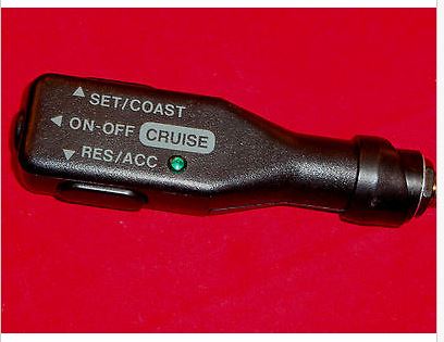
After some research, I settled on a Rostra 250-1223 universal cruise kit. Mine came from the US eBay and cost US $220 with free shipping, including the steering column-mounted control “stalk” (All Rostra units come without any control switchgear, as they offer a number of different options, including either left or right side mounting options for this particular stalk ). I opted for left-side mounting, (Rostra product 250-3742) thinking it would be more out of the way of knees when entering/exiting the car:
Before recounting my installation experience, I want to say that this is not a one-day job. While it is by no means rocket science, and the documentation that comes with the unit is adequate, I found it took a significant chunk of time over 3 days to complete the project.
Tools required are minimal. You will need an electric drill, assortment of screwdrivers, and an angle grinder or hacksaw to modify the mounting brackets.
The first step was fabricating a mounting for the cruise control throttle actuating cable. The instructions tell you to measure the distance of the stock cable travel. Based on my measurement, I followed their advice to add a short extension segment to the cable (provided) using a ball chain, and adding just a single ball’s additional length. They provide a short length of cable with a “noose” to slip underneath the existing OEM cable end at the throttle housing. I opted to connect my noose to the transmission cable fitting, as trying to attach to the actual throttle cable would not provide a straight line to the cruise cable. You can see the cable noose just below the ball chain in the image below:
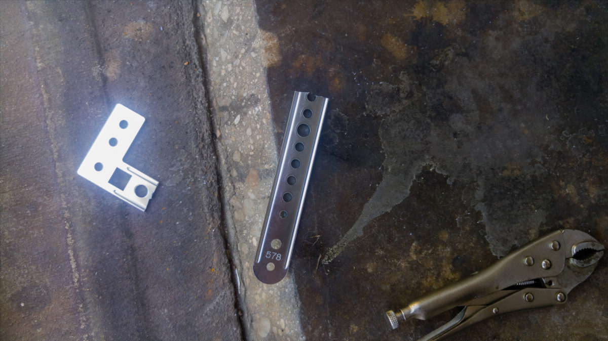
Next, I had to find a way to adapt the provided cruise cable bracket to fit the Figaro. The provided bracket is shown below:

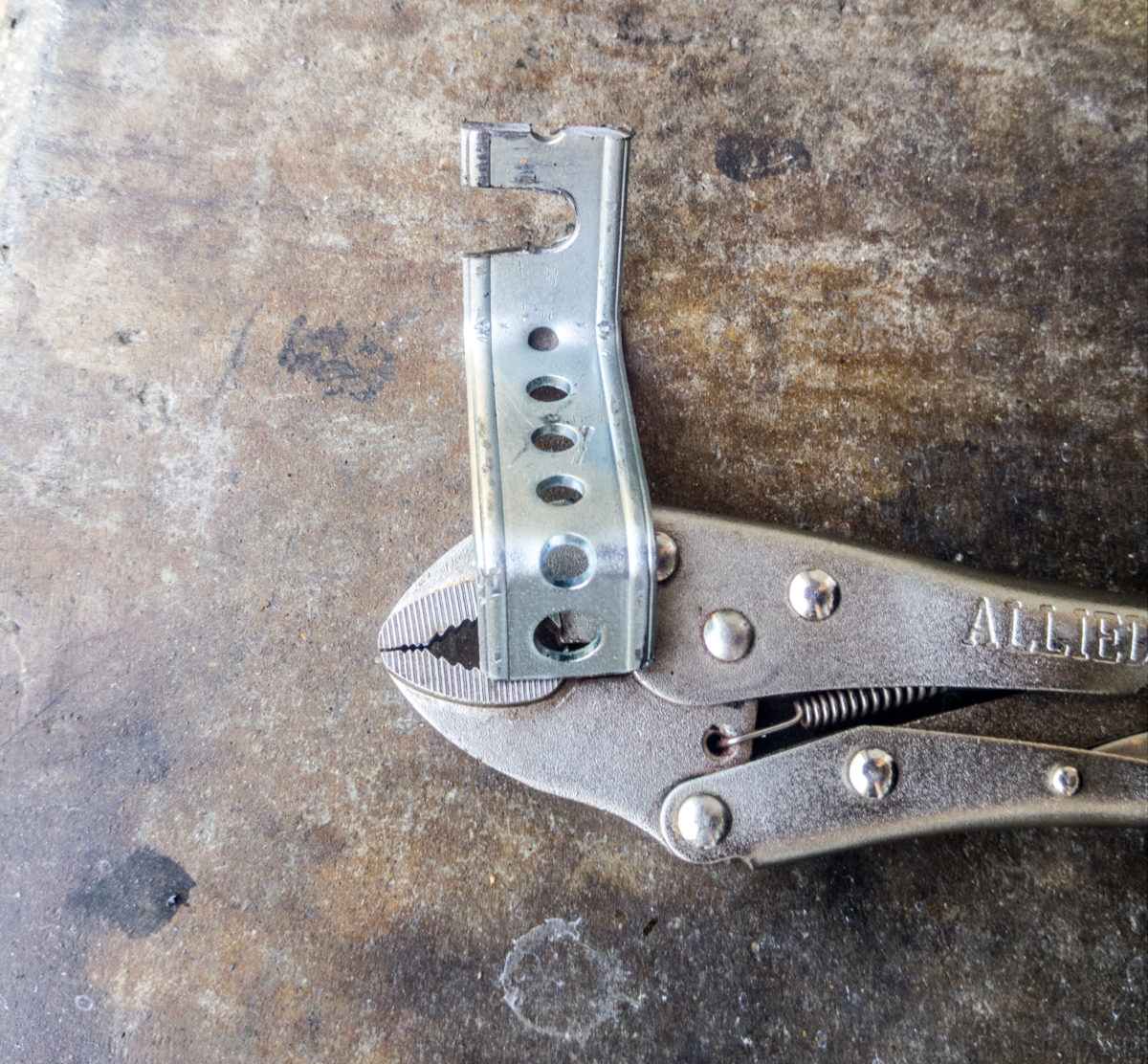
I decided to cut the bracket into two pieces, and then mount the assembly behind the existing shaft/nut of the original throttle cable. I would need the piece with the square hole for the provided nylon cable stop, so I cut it off that main piece, and, as well, cut off the right angle extension which would serve no purpose for this installation:
Customizing the provided bracket for the Figaro

Next, I used the remaining part of the bracket, bending it into a “Z” shape to provide the correct length of the cable to the throttle body. This included drilling a 3/8″ hole to accommodate the diameter of the existing throttle cable threaded fitting, and then cutting a slot out of one side (This is necessary, as the original throttle cable is built as a single piece, and can’t be disassembled, thus the cable mount is slotted as well). This makes installation easier, as it is only necessary to slacken the adjustment nuts on the original cable shaft, and slip the bracket behind, then retighten.
Bracket for Cruise Cable
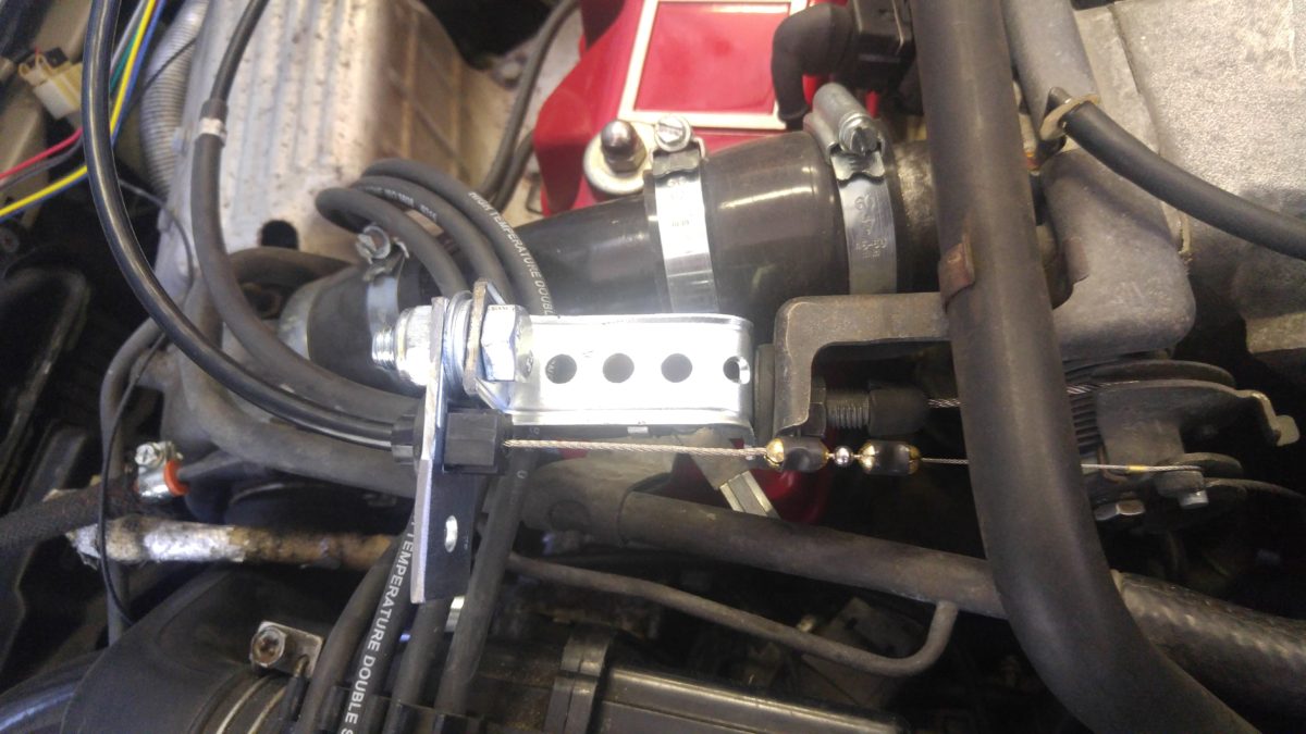
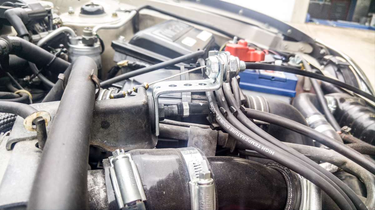
Fabricated “Z” shaped control cable mount, attached under the existing throttle cable mount bolt.
In the picture above, you can see how the cruise cable end is attached to the transmission cable via the little wire cable noose, and the single ball chain extension in between.
I purposefully made the Z shaped bracket a little shorter than the dimension necessary to have the cruise cable be a snug fit without unnecessary slack, then adjusted the final placement with two washers between the “Z” bracket and the bolt on receiver with the square hole for the cable stop.
Next, it was time to find a place to mount the cruise control box under the hood. I considered several options, including adjacent to the battery box on the near side, but I could see that it would be difficult to install and remove as necessary, and the cruise cable would have to make unnatural bends.
Finally, I settled on a spot along the inner fender well on the far side (driver’s) , which allowed a natural curve of the fixed-length cruise cable, and secured by a single screw through the provided and slightly modified control unit bracket:
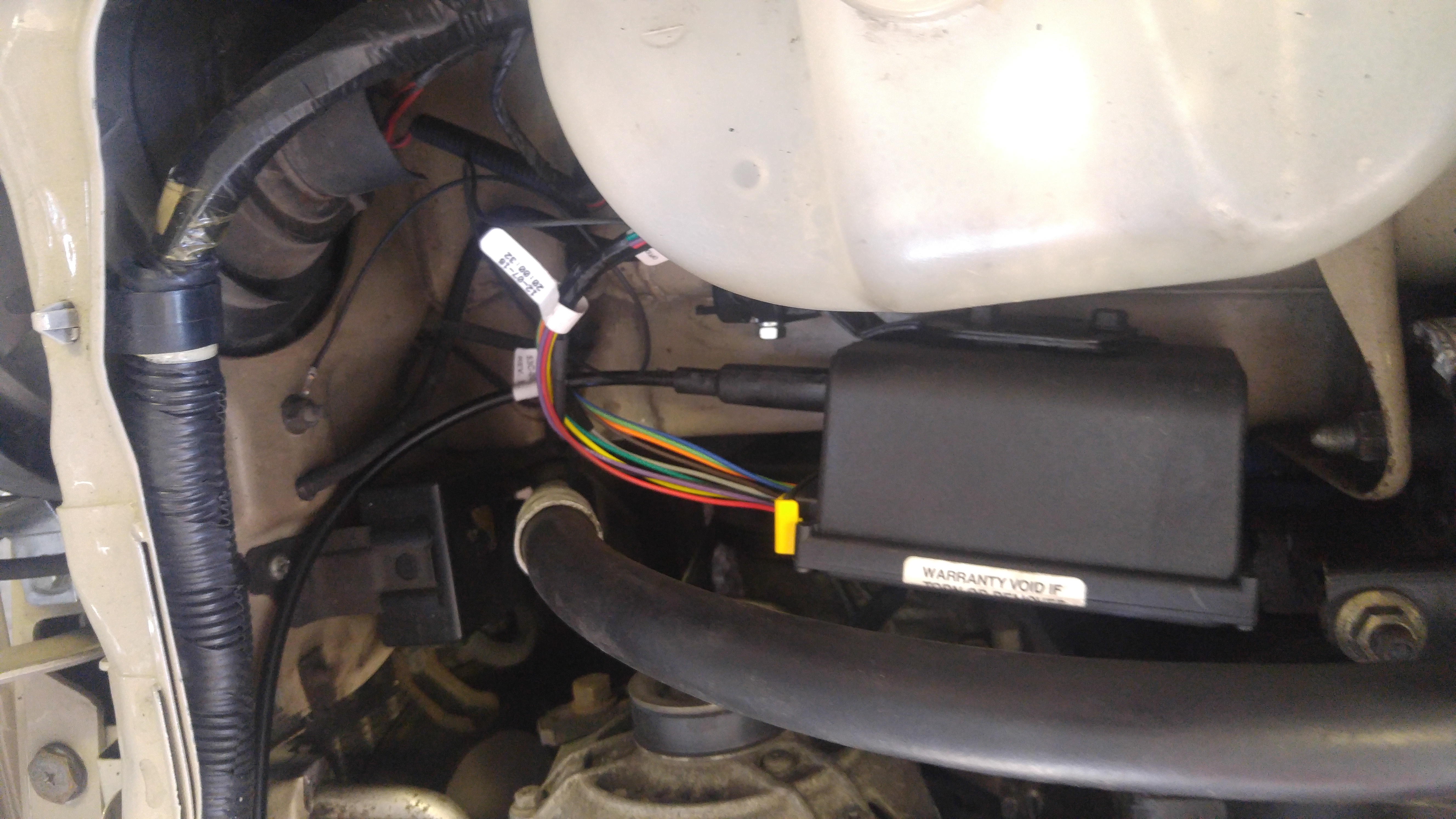
Be sure and set the 12 dip switch settings (according to the installation manual) BEFORE securing the control box, since these will be difficult to see once the box is installed.
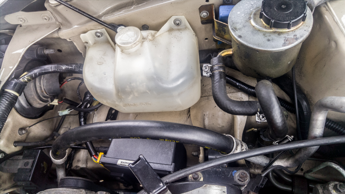
You can see the flexible wire harness covering for the control unit, just underneath the brake fluid reservoir. You can see the white 2-wire connector for the optional Magnetic Sensor (it is laying parallel to the black ground wire on the left side of the photo)
Note the convenient existing stud just behind the headlight unit to attach the required ground for the unit.
This completed the under-bonnet phase of the installation, with the exception of running two wire bundles from the engine bay into the passenger compartment. Nissan was kind enough to provide a big rubber grommet/seal for the massive wiring bundle into the passenger area. The grommet is located just underneath the windshield wiper motor, and, at first glance, looks pretty inaccessible.
However, I found that by removing the 3 screws holding the wiper motor to the bulkhead and pulling the motor out of the way (it didn’t want to come completely out, so I just rotated it), I had just barely acceptable access to that bulkhead grommet. A large flat blade screwdriver made short work of prizing the grommet out of the firewall hole. then I cut a very small slit in the grommet near the center, just enough to push the two 4-wire cruise harnesses through the center, and into the passenger compartment. One of those very long nose pliers came in handy here to both push each connector and bundle through, then grasp it from the other side (under the driver footwell) and pull it on through.
the whole process of feeding the wires through to the interior took a mere 10-15 minutes, and I was done with the worst part of the install.
This modern-day unit is capable of receiving vehicle speed input from the ECU, via the VSS (vehicle speed sensor) output. However, as most of you know, the Figaro’s ECU pin-outs remains mostly a mystery to us English-speaking-only mortals. In spite of much encouraging help from several Figaro owners on decoding the ECU, I finally came to the conclusion that, even if I could identify the VSS output, there were just too many variables to expect a successful installation using this method.
Fortunately, Rostra does provide an alternative for older cars (and, 1991 is definitely pre-OBDII ECU standards, so who knows what might be lurking in these older vehicle electronics). They offer an optional, old-school, magnetic pickup unit. This works by gluing a couple of magnets to one of the front drive axles, then a sensor-on-a-bracket reads those magnets passing by, and transmits the appropriate signal to the cruise control unit to report vehicle speed. This is the way virtually ALL earlier cruise control units worked. While not the most elegant solution (and adding an additional $44 US to my project cost), it seemed like the coward’s safe way out. The Rostra unit is part number 250-4165, and will make the final part of the installation simple and trouble-free. In fact, the provided harness with the cruise control unit already has a 2 wire connector to accommodate that sensor, and the optional unit comes with clear instructions as to how to set the dip switches on the control module to accommodate the axle pickup unit.
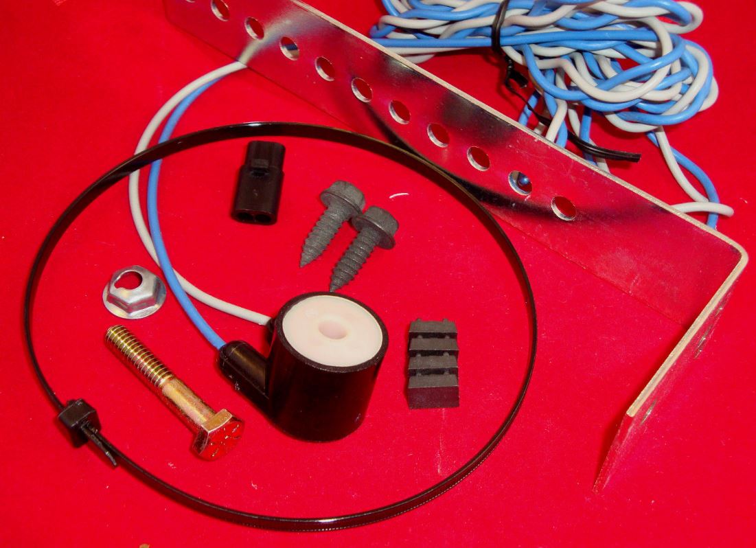
Magnetic speed sensor, with the provided 4 magnets for the axle
The next step was installing the control stalk on the steering column. The Figaro lends itself handily to this task, since the plastic upper and lower coverings are easily removed by unscrewing the 7 screws which secures the lower shroud to the upper. And, there is plenty of room under the covers for the control switch wiring.
I chose to mount my switch into the upper shroud, just behind the wiper stalk on the left side of the steering column. This merely requires drilling a 3/8″ hole at the desired location, then slipping all the wires through the hole and tightening the hold-down nut on the backside.
The 6 wires from the control unit with their pre-crimped pins, are then inserted into the 4 pin and 2 pin connectors respectively. There is ample documentation and diagrams to aid in getting the correct wire (by color) into the proper slot, but take your time, as these pins are one-way only.. once you push it in, it’s there for good!
The newly attached connectors then plug right into the harness which has previously been fed from the engine compartment.
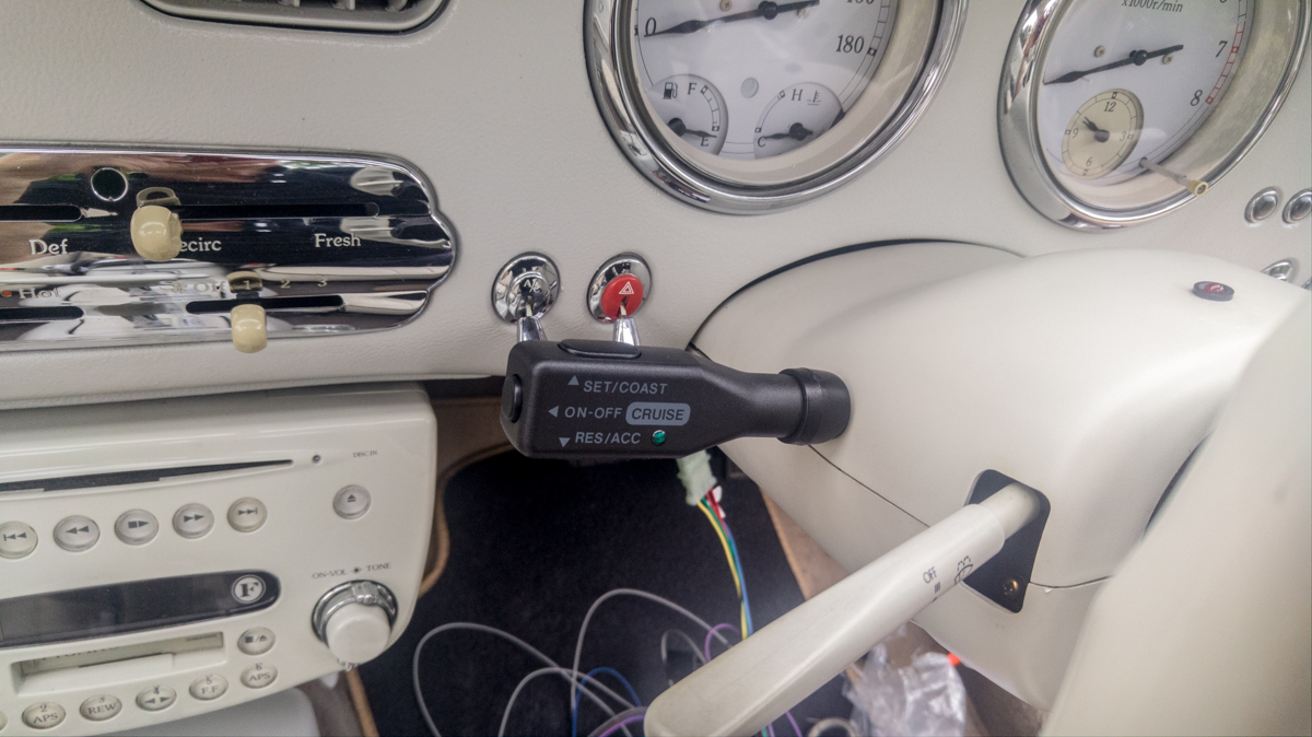
Ignore the spaghetti wires under the column.. those were all neatly tied away after the installation was complete
In hindsight, I might have chosen to mount the control stalk at a little different angle, maybe even attaching to the LOWER column covering rather than the UPPER, since the unit partially obscures the A/C and emergency flasher switches (but doesn’t impede their access)
Next, comes attaching the two brake sensor wires to the brake switch (this is critical to allow the cruise control to disengage when the brake pedal is pressed). I found this to be the most cumbersome task of all, as there is very little slack in the 2-wire brake switch connection to work with. The switch itself is easy to identify, mounted just above the brake pedal arm.
NOTE: Power to the brake switch is ALWAYS live, even with the ignition switch off (i.e., the brake lights can be actuated without turning on the ignition key), so it is best to follow the instructions and disconnect the battery while performing this step.
My method: I unplugged the connector from the brake switch (just depress the lock bar on the front of the connector and pull it free), then I cut the two wires leaving only about 3/8″ of length on the connector end. This allowed me to put the connector on the bench, solder and shrink tube a slightly longer wire to each of the connector leads, then I used a crimp butt connector to capture both the original switch connector wire AND the respective wire from the cruise unit (it is the RED and VIOLET wires. The RED wire from the cruise control goes to the orange/black wire at the switch, the Violet, of course, goes to the other wire). Finally I crimped the other end of each butt connector back to the the wires from the stock harness that originally attached to the brake switch connector. DONE!
The final step underneath the dash panel is connecting the cruise control BROWN 12V+ wire to a position within the fuse box on the driver’s sidewall. This (brown) wire is provided with a clever metal connector on the end that merely slips behind an existing fuse in the box and is then held in place when the fuse is re-installed. You will need to select a fuse position that provides power ONLY when the ignition key is turned on. I found that the 2nd fuse from the outside, a 15 AMP one, provided that capability. You will want to slip the connector on to the leg of the fuse which comes from the battery power, and not on the fused side (i.e., you don’t want your system to draw current through the existing fuse, as the provided harness has its own fuse holders and fuses integrated into it). I confirmed that the POWER side of the fuse box is the row of connectors on the TOP side of the box.
With this task done, all that is left is to use the provided zip tie straps to bundle all the excess wire and tie everything up out of the way underneath the dash.
As previously noted, I decided to not try to experiment with finding a workable VSS (vehicle speed sensor) output from the Figgy’s ECU (if such a signal even exists on this 25 year old vehicle). Instead, choosing to spring an additional $44 US for the optional magnetic sensor. The optional kit comes with small magnets and a heavy duty tie wrap strap.
For front wheel drive cars, you attach 2 magnets at 180 degrees apart on the axle CV joint, right where it exits from the transmission, and then secure them permanently with the tie wrap strap. Then a separate sensor with an included bracket is installed about 1/2″ away from the rotating CV joint. The sensor detects the magnetic pulses, and translates that into a vehicle speed, used by the control unit to maintain your set speed. Of course, with the cruise control box mounted on the driver side of the engine bay, it made sense to mount the magnets and sensor on the DRIVER side CV joint.
I used the bolt which holds the transmission shield in place as a perfect spot to attach the sensor pickup bracket, cutting off the excess bracket length, and drilling a hole in the bracket at the appropriate spot to position the sensor the required 1/2″ from the rotating magnet sensor.

You can see the tie wrap around the green CV joint, holding the 2 magnets in place
The 2 wires permanently attached to the sensor are terminated on the other end with pin connections, which can then be plugged right into the provided connector on the control harness, right near the control box.
Use tie wraps to carefully secure the excess wire away from the exhaust and any moving parts on the engine, and THE JOB IS COMPLETE!
After experimentation, I found the following dip switch settings to work best with the Figaro, using the optional magnetic speed sensor (dip switches located underneath the rubber housing on the face of the control unit)

Additionally, there will be two unused wires in the interior cabin harness:
The GREY wire is to connect to the ECU VSS output (which we have determined to be a mystery), and is superceded by the 2-pin connector in the engine compartment for direct connection to the “optional” magnetic speed sensor unit. This wire can be cut back so as to not interfere with anything else under the dashboard.
The BLUE wire is for connection to the ECU TACH output, which several Figaro contributors believe to be the #3 pin at the Figaro ECU (White/Red). This connection is solely to disconnect the cruise control in case the transmission is inadvertently shifted into neutral while the cruise control is engaged (by detecting a rapid increase in engine RPM). This seems an unlikely occurence, and even the Rostra technician I talked with seemed to think this was by no means a necessary connection. In light of being unable to fully verify the ECU pin outs, I elected to disregard this connection. Other owner/installers might want to give this a shot.. the ECU is located behind the plastic panel in the passenger outer footwell.
I was thrilled when, on first test drive, the unit functioned perfectly, including brake pedal disengagement (likely a first for me). I am very pleased with the performance of the unit, the documentation, and the manufacturer’s support assistance!
Phil Auldridge – April 2017