Our Figaros have a reputation for reliability. And, why not? Japanese technology and an under-stressed mechanical platform promise years of trouble-free operation.
Nevertheless, as with all things mechanical, from time to time, things do need attention.
Only a couple of short months after importing our Topaz Mist Figgy from the UK, we started hearing a repetitive ticking sound from under the bonnet. Further investigation revealed the sound was coming not from internal engine issues, but somewhere near the flywheel/driveplate. As time wore on, the sound became louder and louder, until it became clear that an internal inspection was necessary. Finally we were able to see cracks forming in the actual drive plate itself, and opted to remove the transmission to resolve the issue.
With no complete English language factory shop manual available, I had to rely on long distance guidance from the good guys at The Figaro Shop and a copy of the Haynes Nissan Micra Shop Manual(1883-1993 version, frequently available on Amazon used for just a few dollars). I do highly recommend that owners obtain a copy of that Haynes manual, as much of the mechanical bits of our Figaros are similar or identical.
This guidance then, applies to any need to remove the transmission (which can be easily accomplished with engine remaining in place), whether it be for replacement, repair, or to gain access to the flywheel area.
And, it should be noted that, while the list of steps can initially look daunting, none is overly complicated or complex, and easily accomplished by a home mechanic with basic skills and tools. I do want to stress that the easiest setup for this task would involve a 2 post (preferable, as I used) or 4 post car lift, although I do believe it can be achieved with the car up on jack stands as well. I decided to spring the $180 for an extendable transmission jack/lift, and after completing the job, I consider that money very well spent.
You WILL need a helper, at least for that final step of removing and reinstalling the transmission itself.
Obviously, if you are opting to tackle this job with the car on jack stands, PLEASE be careful and use prudence. Install back-up supports where possible. If you are jacking up just the front of the car, make sure the emergency brake is fully set and the rear wheels are blocked up.
Here goes.. just follow these steps in sequential order:
While the car is still on the ground:
- Disconnect the negative lead of the battery for safety
- Remove the airbox assembly.. (possibly not absolutely necessary, but you will be glad you took the time to do it)
- unscrew the 4 screws for the cover and lift off
- disconnect the multi-terminal connector from the airbox-to-engine duct
- with a 10mm socket on an extension, remove the outer (near wing) and forward (near battery box) hold-down bolts for the air filter box.
- loosen the clamp for the airbox duct at the engine and free up the duct
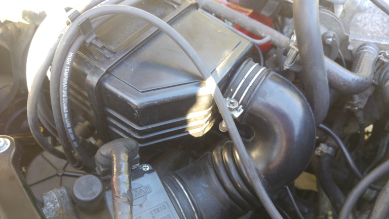
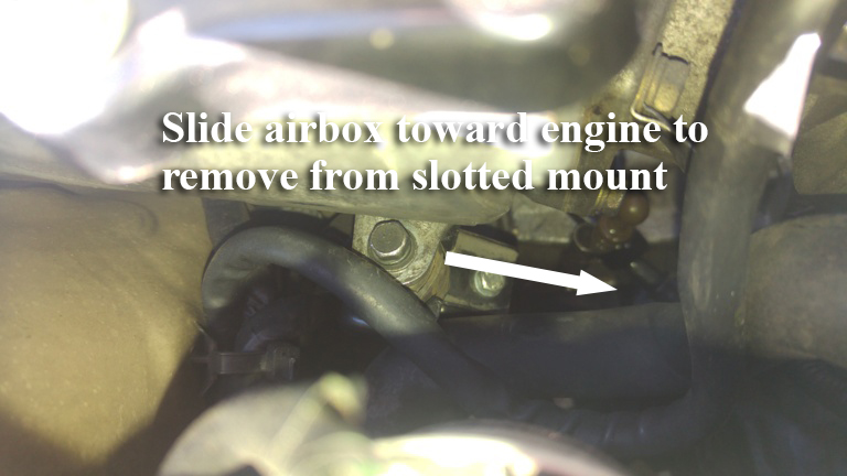
- there is a 3rd hold down for the airbox, on the aft/engine side.. it fits in a slotted receptacle, and with the other 2 bolts removed, you should be able to just push the entire box toward the engine and free if from the slot without further loosening the bolt, then lifting the whole assembly out:
- Remove the main battery power lead and smaller plug-in wire from the starter, then remove the upper and lower bolts holding the starter to the bell housing using a 14mm wrench, and lift the starter out of the engine bay
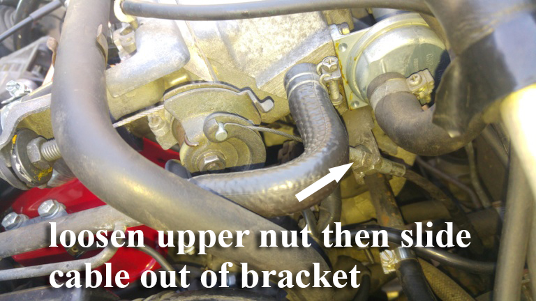
- There is a kickdown cable running from the throttle bracket on the engine to the transmission. Loosen the upper nut (with a 15mm wrench) on the cable adjustment (leave the lower intact so as to not alter the adjustment), and slide the cable out of the bracket, you will then be able to disconnect the cable end from the throttle mechanism. It is NOT necessary to remove this cable at the transmission itself. Just lay it over the transmission when removing the tranny itself:
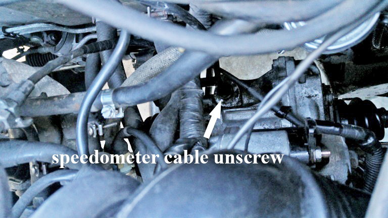
- The speedometer cable screws into the transmission just behind and below the starter. Unscrew the knurled fitting (it is NOT necessary to remove the 10mm headed bolt on the hold-down), and pull the cable out of the way:
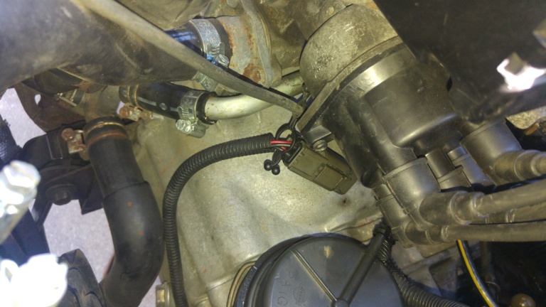
- Disconnect the multi-pin connector to/from the transmission:
- With a 12mm socket remove the two upper bolts that connect the transmission bell housing to the engine block (don’t worry, there are 2 additional bolts into the engine, plus two transmission mounts still holding it all together
- Finally, before lifting the car off the ground, loosen the front wheel lug nuts AND break loose the 30mm-headed stub axle nut (discussed below), otherwise you will certainly need an air impact gun to remove it.
Now it is time to get the car up on the lift (or jacked up)
- Remove both front wheels
- Remove the plastic shield on each side that goes around the drive axles
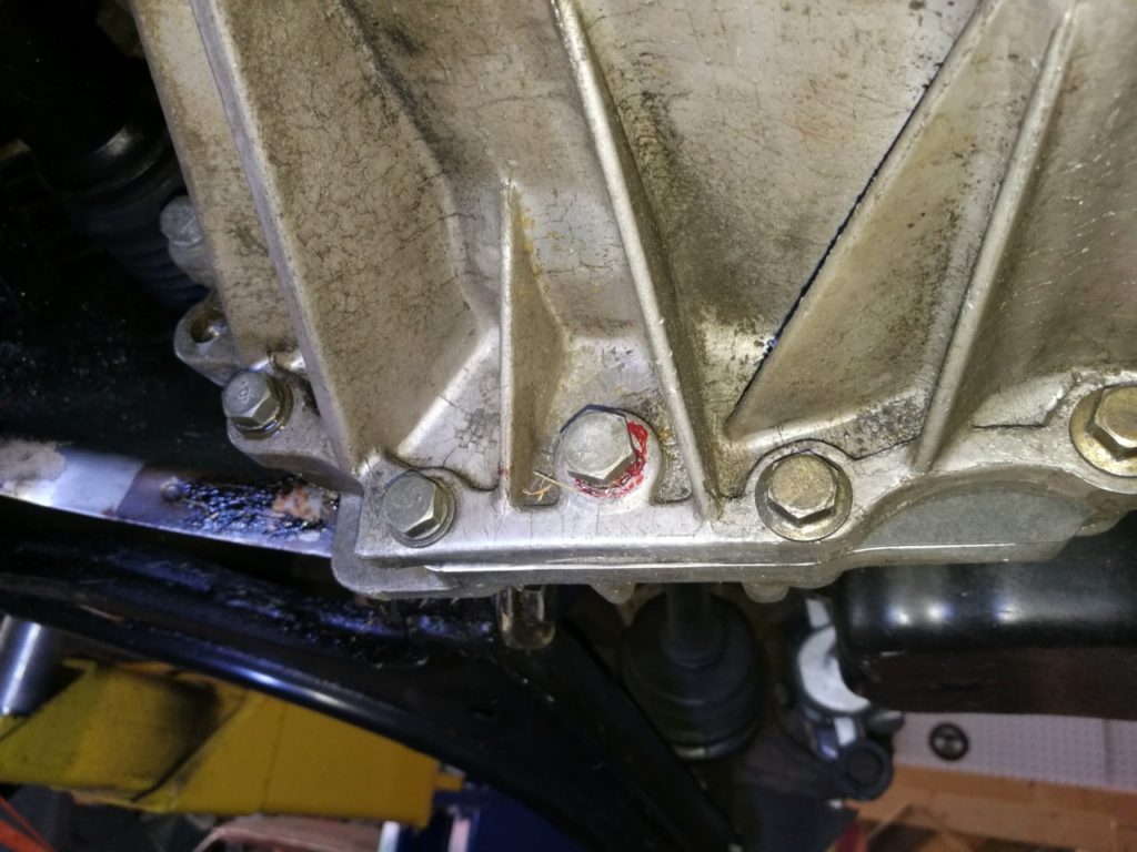
- Drain the transmission fluid. The drain plug is NOT on the bottom of the pan, but rather on the lower part of the tranny case facing the engine (shown in the photo surrounded by red sealant. You have to look for it and remove with 14mm wrench:
- Disconnect the two transmission cooling lines at the radiator by loosening the hose clamps and pulling off. Be prepared to catch some additional leaking fluid:
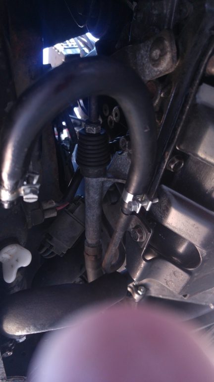
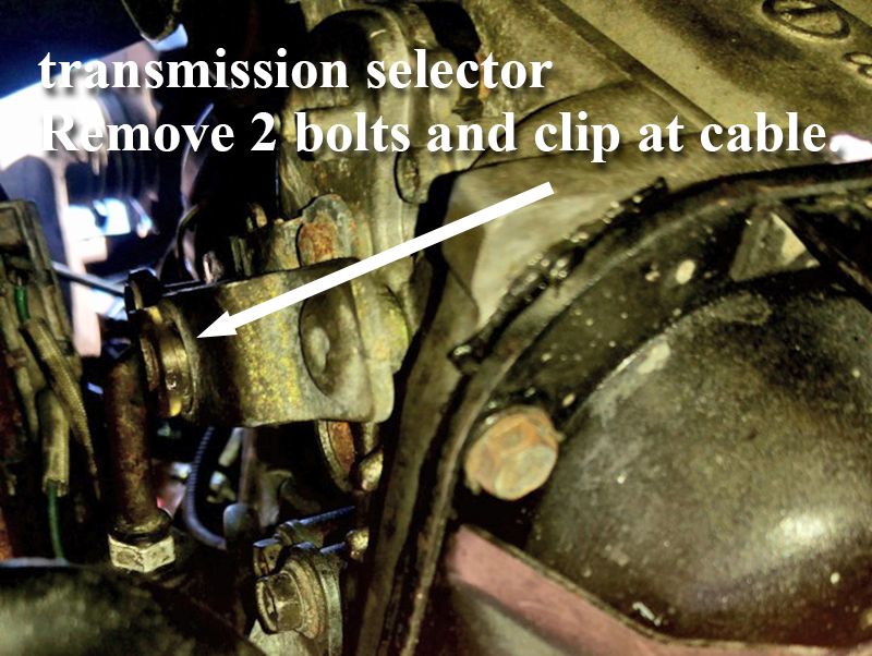
- Disconnect the 2 12mm-headed bolts holding the transmission gear selector cable (front, outboard side of transmission), then remove the clip that holds the cable itself to the transmission selector arm, and tie the assembly out of the way:
- The transmission drive plate/ring gear/flywheel is connected to the torque converter via 3 small 14mm head bolts (Yes, just Three!). These bolts are accessible one at a time through a small access circle (about 1 inch in diameter) in the metal shield between engine and bellhousing. This access port can be seen on the AFT side of the engine, near the starter:
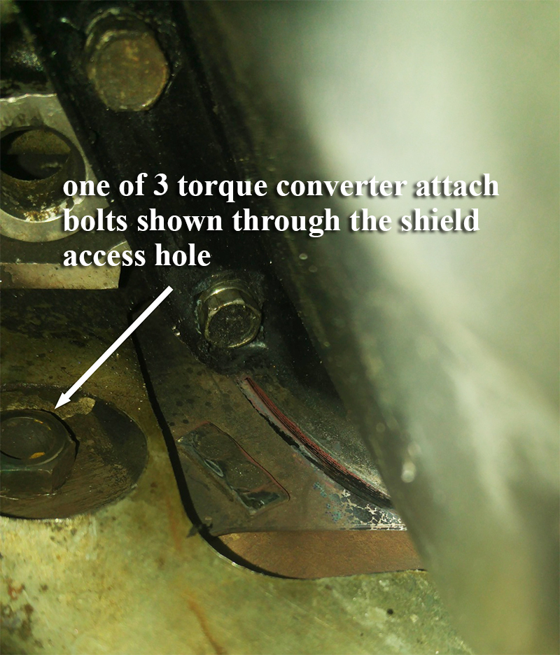
Use a 19mm socket on the forward crank pulley of the engine to slowly turn the engine by hand until one of the 3 bolts appears in the access hole, then while an assistant holds the crankshaft at the front pulley, remove the bolt. Proceed similarly until all 3 bolts have been removed.
- It is not necessary to remove the exhaust pipe, but it is a possible consideration to give a bit more access to the whole process.
- On the LEFT SIDE wheel only:
- remove the cotter pin, safety lock, and 30mm headed nut from the end of the axle that protrudes from the wheel hub (brake rotor). If you haven’t loosened this nut previously, you will likely need an impact air gun
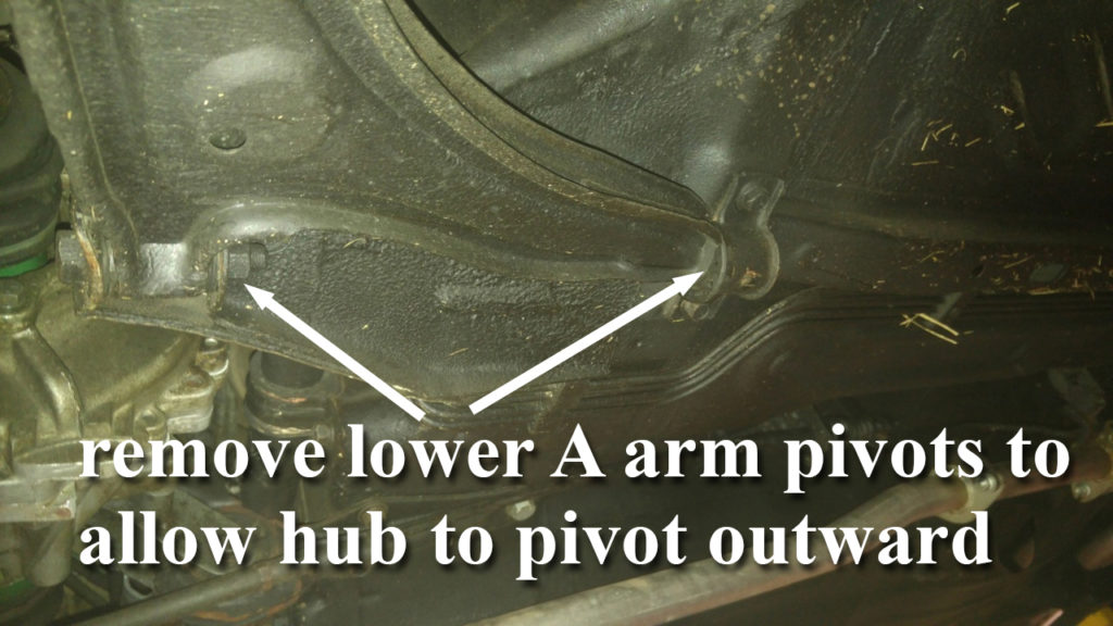
- disconnect the 19mm-headed forward pivot bolt and 2 aft strap hold-down bolts (14mm head) from the A-arm suspension (there will be no spring tension on this arm)
- You should now be able to just swing the wheel hub upwards, freeing the outer end of the axle, the other end to remain in the transmission. If necessary, tap on the end of the axle to free it from the hub, taking care not to damage the threads.
- Use a piece of wire to pull the wheel hub and A arm aft in the wheel well to not interfere with transmission removal
- On the RIGHT SIDE only:
- Remove the lower A arm pivot bolts exactly as done on the left side and pictured above
- The axle on this side must be removed at the transmission rather than at the wheel, because the axle runs through the thin metal shield between the engine and transmission, and would interfere with lowering the transmission from the engine
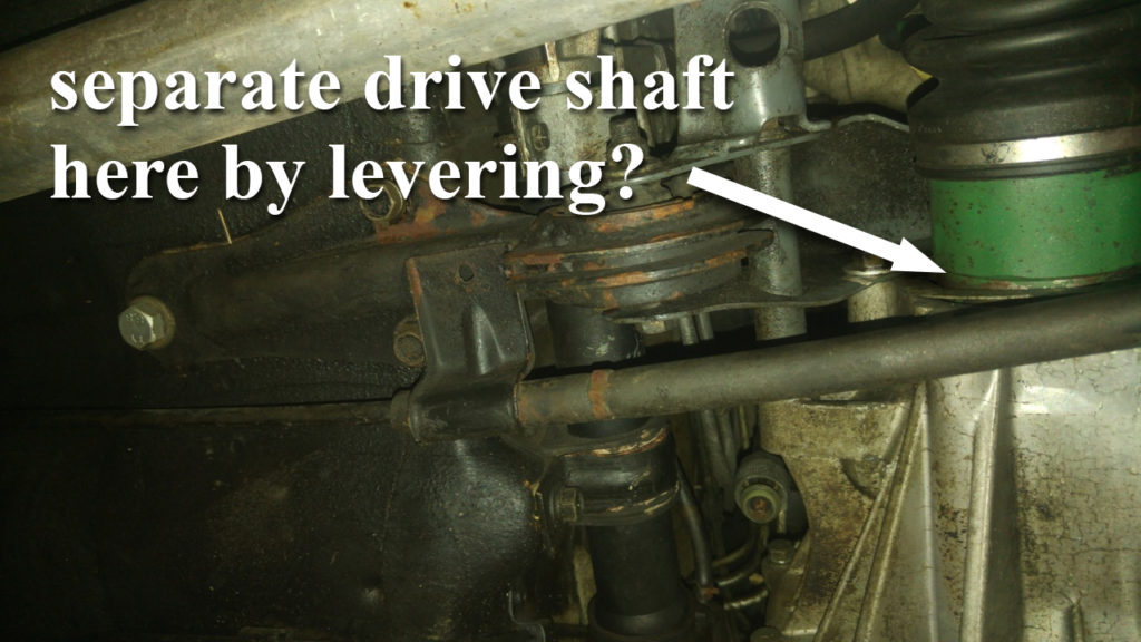
- The axle shaft is loosely held into the transmission with a small circlip. It takes just a small bit of force to overcome that circlip friction and lever the shaft out of the transmission. In fact, there is a slot built into the bottom of the axle joint just for that purpose:
 Now you will be able to pull the axle shaft free of the transmission, leaving it attached at the outer end to the wheel hub, and tie the entire axle/wheel hub assembly out of the way.
- The Haynes manual mentions placing a dummy shaft into the now-open hole in the transmission. They mention possibility of a gear falling down into the case otherwise? As a precaution, I cut a 3.5″ length of 3/4″ steel pipe and slipped it into the opening just as soon as I pulled the axle free. Don’t make it too long, as then the protruding pipe would interfere with the shield and prevent lowering of the transmission.
- Now it is time to support the engine (we will be removing one of the 3 engine pivot supports) by placing a 2×6 under the oil pan then supporting it with some sort of adjustable stand.
- Support the transmission with an up-down adjustable transmission jack that can be rolled as needed when time comes to remove the transmission
- Remove the Engine/transmission pivot support at the aft of the engine. The best way to do this is to remove the three bolts that secure the mount to the body, and additionally remove the 3 bolts securing the mount to the transmission. Do NOT remove either of the 2 pivot bolts holding the rubber mount.. these will stay with the entire mount assembly when removed. Note that the forward-most bolt serves to secure the bell housing to the engine block as well. At this point, there is just one remaining bolt holding the bell housing to the engine.
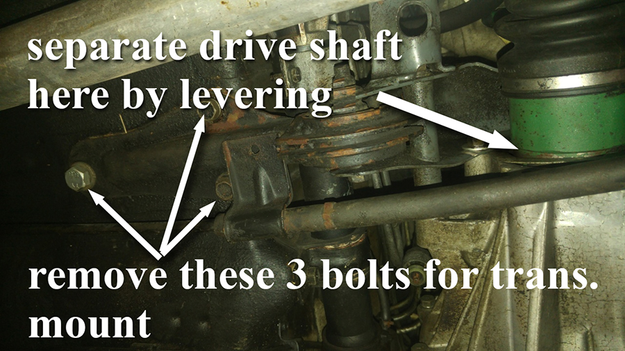
- Remove the center pivot bolt from the outboard (wing) transmission support. Additionally, remove the 3 bolts that secure that support bracket to the transmission and set the whole mount assembly aside
- Note, it is NOT necessary to remove the forward mount that is positioned at the front of the engine, just at the engine/transmission split line. Leaving this intact will help support the engine, and will not interfere with transmission removal.
- At this point, the only thing securing the engine to transmission is a single 12mm-head bolt on the front side of the engine at the lower edge of the engine casing. Go ahead and remove this bolt, and the transmission is ready to come out.
- It is a very tight fit between the transmission and the outer bodywork as you began working the unit toward the wheel well (you DO have an assistant, right?). Some sort of lever between engine and transmission can assist in moving the transmission aft and separating the 2 pieces
- Note that there is a locating dowel pin on the back side of the engine block, a bit above the starter location. This is by design a very snug fit, and may very well resist being separated there, so a judicious application of lever in that area well assist in freeing the transmission from engine
- Once the bell housing edge can be seen to be clear of the ring gear on the drive plate, the transmission assembly can be deemed to be fully free of the engine, and can be lowered down and out.
- CAUTION! Make sure that the torque converter stays with the transmission (i.e., is not allowed to fall out during extraction of the whole transmission). This should not be a problem unless the transmission were to be tilted in a way to allow it to fall out.
There you have it! The complete process in a nutshell. The guys at The Figaro Shop told me they allocate about 4 hours to perform this job, but I estimate it took about 10 hours with this amateur!
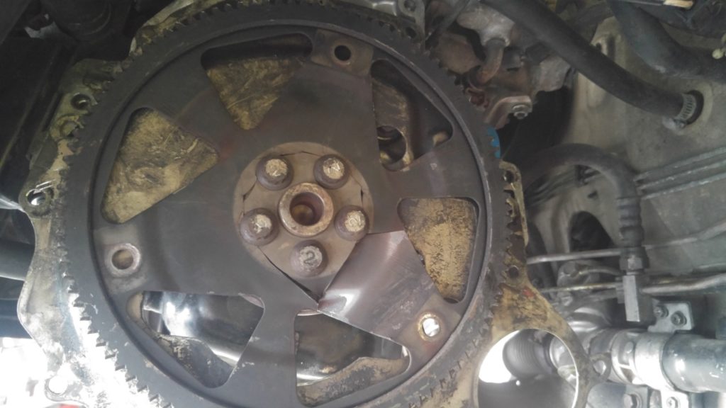
Once we had the transmission safely out of the car and on the ground, we had a chance to inspect the condition of the drive plate on the engine. Here is what we found.. the entire center of the plate had cracked, failed, and separated from the outer arms. It appears that the wide shoulders of the attach bolts were the only things holding the outer part of the drive plate in place (gulp!):
Once removed from the car, the whole thing fell into 2 pieces:
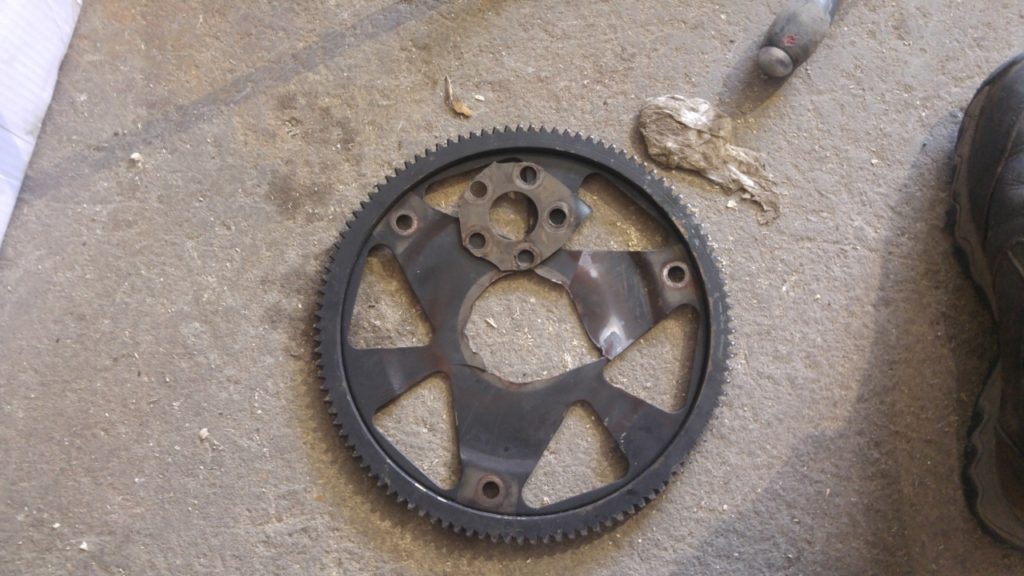
A thousand thanks to Toby and his crew at The Figaro Shop for sourcing a replacement drive plate for us.
INSTALLING TRANSMISSION IN THE CAR
Reinstalling the transmission back into the car is pretty much the reversal steps of the removal process, with the following additional consideration:
- Before mating the transmission back to the engine, be sure the drive plate is positioned so that one of its mount holes will be visible through the access hole in the shield plate (remember, that 1″ hole near the starter, on the engine side?). Then position the threaded bosses in the torque converter to correspond, so they will match up when the transmission is offered up. I believe you will find that with one of the bolt holes on the drive plate positioned straight down, one of the other will be visible through the access hole.. so, you can just position one of the threaded bosses on the converter to point straight down as well.
- We found it easiest when positioning the bell housing in place, to first catch the forward lower bell-to-engine block attaching bolt, as it is easily accessible from below. Then once the locating dowel is mated on the other side, temporarily insert the AFT lower bolt (the one that ultimately will connect through the aft transmission pivot mount).
- If you have supported the engine with a vertically adjustable jack or lift, you may find it helpful to raise or lower the engine slightly to help align the aft of the engine block with the bell housing mating surface.
- Don’t re-install the starter until you have the drive plate bolted to the torque converter, as you may have to move the converter a bit to line up the bolt holes, through the starter opening in the bell housing
- Don’t forget to reconnect the 3 drive plate to torque converter bolts in reverse fashion. I was unable to find a torque setting for these bolts, so I used a good strong thread locker and used my best judgement when tightening.
- Don’t forget to refill the transmission with fluid!
phil auldridge – austin, texas – february 2017